Match a Rough 3D Camera to a Location Photograph Without Inventing Measurements
Match a Rough 3D Camera to a Location Photograph Without Inventing Measurements
A camera match can help a pitch show how a proposed object, performer, or rough set might sit in a photographed space. It cannot, by itself, tell you the room's dimensions or prove that the proposed camera position is available on location.
The useful result is a perspective model with named assumptions: which edges you treated as parallel, which directions you treated as perpendicular, where you placed the image's principal point, and what—if anything—established scale. A convincing overlay without that record is difficult to distinguish from a plausible guess.
fSpy estimates approximate camera parameters from controls placed on a still image.[^1] The distinction between approximation and measurement is the subject here. The worked example below uses an original, mathematically projected box so its assumptions can be checked. Its numerical results were generated and tested; the corresponding native fSpy-to-Blender demonstration has not been executed. Do not treat this example as a tested importer walkthrough or a surveyed location.
Decide what the pitch needs the match to establish
Suppose a scene places a performer at the far end of a narrow room, with a large object between the performer and the camera. A rough camera match could help compare two compositions: the object concealing the performer, or leaving a line of sight beside it.
That is a question about the proposed image. It is not yet a claim that the object fits through the doorway, that the crew can work behind the camera, or that the photographed floor is level.
Write the intended use before calibrating. For example:
Perspective study for the proposed foreground obstruction. Room dimensions and camera clearance are unverified.
This gives the exercise a stopping point. You need enough geometry to compare the visual relationships in question. You do not need to invent a complete building model to make the image feel more finished.
If the decision instead depends on the physical distance between the camera and a wall, collect appropriate location measurements. A camera match may accompany them, but it should not substitute for evidence the image does not contain.
Choose a photograph the model can reasonably describe
fSpy's documented assumptions are a useful filter. Its guides represent parallel lines in the world, and the different vanishing-point directions are treated as perpendicular. Its basic model suits perspective images with little lens distortion; the documentation warns against severe distortion, altered perspective, orthographic images, and stitched panoramas.[^1]
For a room, look for structural edges whose relationships you have a reason to trust. Two edges of one rectangular panel can be a better starting point than a pipe and a shelf that merely look aligned. Do not choose a shadow as a wall direction unless its geometry is independently understood.
Prefer long, clearly visible edges to tiny details with uncertain endpoints. Keep unused edges available for a later check. A solution that only agrees with the controls that created it has not yet faced a different part of the image.
Ask for the original image and its crop or correction history. A listing photograph may have been straightened; a phone panorama may look like an ordinary wide shot. When that history is unknown, record it as unknown. Do not “correct” a photograph until it fits your model and then cite the fit as proof of the model.
If the available image is unsuitable, the useful next move may be a new photograph or a simpler, explicitly illustrative blockout. More time adjusting guides will not establish that incompatible source material obeys the required geometry.
What two vanishing points actually give you
A vanishing point describes the image direction of a family of parallel lines. In a suitable room photograph, one family might run across the floor and another toward the back wall. Their lines may intersect far outside the image; the intersection need not sit inside the crop.
The original exercise uses this wireframe box:
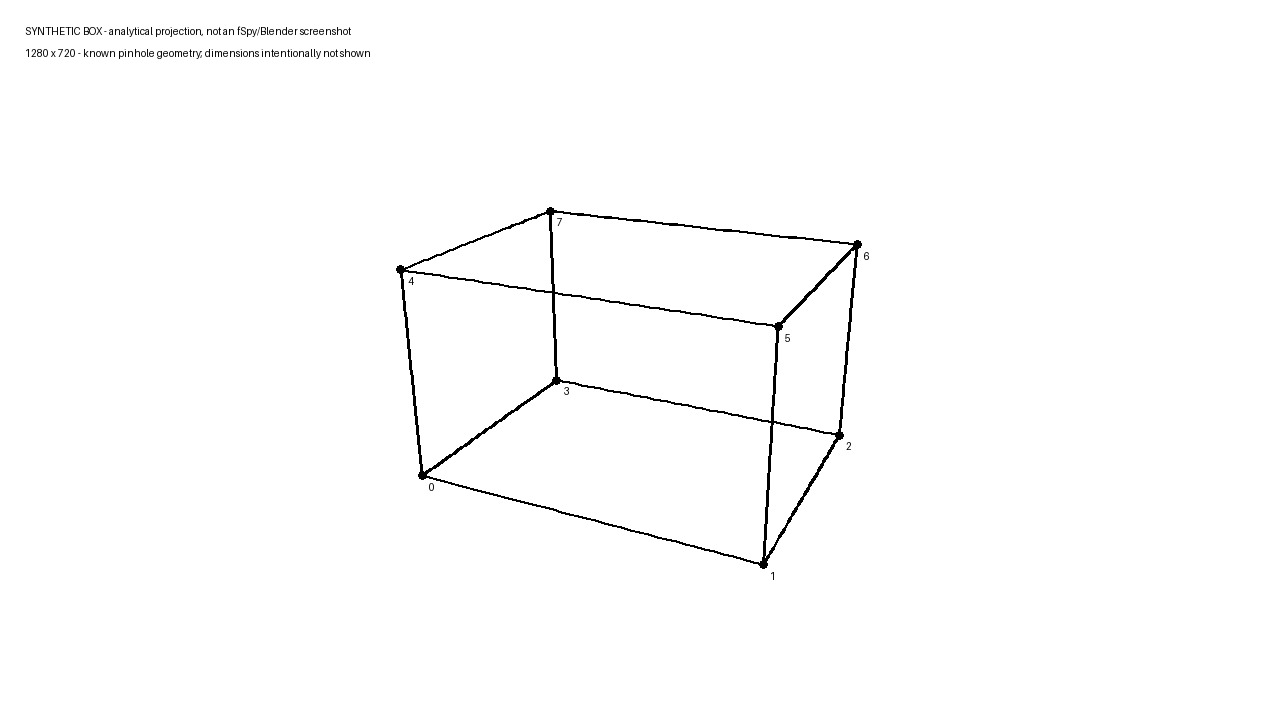
An analytical perspective projection, not a real location or a native application screenshot. Its answer key defines the box as 4 × 3 × 2.4 meters; that scale is withheld during calibration.
Use floor edges 0–1 and 3–2 for the first family. Use 0–3 and 1–2 for the second. Leave the four vertical edges out of the solve.
The image is 1280 × 720 pixels. In the answer key, the principal point is at (640, 360) and the focal length is 900 pixels. The principal point is the coordinate through which the camera's optical axis is represented in the image; it is a camera-model parameter, not a compositional point of interest. OpenCV's pinhole formulation distinguishes this point from focal length and from the camera's position and orientation.[^2]
Here is the useful relationship for this deliberately restricted model. Let v1 and v2 be the two vanishing points, c the known principal point, and f the focal length in pixels. Assume square pixels, zero skew, and perpendicular world directions. The direction vectors corresponding to the vanishing points are proportional to:
(v1.x − c.x, v1.y − c.y, f)
(v2.x − c.x, v2.y − c.y, f)
Perpendicular vectors have a zero dot product. Therefore:
f² = −[(v1.x − c.x)(v2.x − c.x)
     + (v1.y − c.y)(v2.y − c.y)]
This is a derivation for the stated assumptions, not a claim that every pair of crossing lines determines a lens. If the expression gives a negative value for f², the inputs do not produce a positive real focal length under this model. Reconsider the directions, principal point, or image rather than reporting an imaginary “measurement.”
In the supplied numerical fixture, line intersections recover vanishing points at approximately (-1423.04, -4.06) and (1096.87, -4.06). Substituting them and the known principal point gives 900 pixels. The script checks the result against the hidden input.
That is exact synthetic-coordinate recovery. It is not a claim that clicking the same guides by eye will achieve that precision. Nor is 900 pixels a 900 mm lens: the number here belongs to the image-coordinate model, not a physical lens label.
A crop can preserve the lines and change the answer
Now crop the source image asymmetrically. Remove 180 pixels from the left, 60 from the right, and 30 from both top and bottom. The result is 1040 × 660 pixels.
No object moves. No lens changes. Every retained image coordinate simply shifts by the crop's left and top offsets.
The original principal point (640, 360) therefore becomes (460, 330). But the center of the cropped image is (520, 330). Those are not the same point.
Recalculate using the correctly shifted principal point and the recovered focal length stays at 900 pixels. Assume the new image center instead, and the same two sets of guide lines produce about 842.63 pixels.
The wrong answer is not a software crash. It is a valid-looking numerical result obtained by supplying a wrong assumption. The chosen guide families still meet at their observed vanishing points, so simply looking again at those families may not expose it.
fSpy's tutorial specifically addresses an off-center principal point after an asymmetric crop. It allows a known principal point to be placed manually, or an additional perpendicular vanishing direction to constrain it in the applicable mode.[^3] Do not assume that finding the center of the delivered JPEG has recovered the center of the original camera image.
Both images and the crop coordinates are published with the fixture. That provenance is what allows the principal point to be shifted correctly. With an unknown crop from an unknown original, the same certainty is unavailable. You would need additional constraints or a more qualified result.
Resizing is another transformation to record. The pixel-valued camera parameters must change with image scaling; OpenCV's documentation makes this explicit.[^2] Avoid solving one image and importing a differently cropped or resized version without accounting for the transformation.
Test directions you did not use to obtain the solution
The cropped-image experiment has a useful advantage: four vertical edges were withheld. Once two perpendicular direction vectors have been recovered under the assumed camera model, their cross product supplies a third perpendicular direction. Project that direction to obtain its predicted vanishing point.
For each unused vertical edge, draw a line from its lower endpoint toward that predicted vanishing point. Measure how far the upper endpoint falls from the line. This asks whether the camera model predicts a different observed direction, rather than checking its own input again.
Using the correct cropped principal point, the errors are effectively zero at the precision of the calculation. Using the incorrect centered assumption, the four errors range from approximately 3.50 to 9.81 pixels.
The exact numbers apply only to this fixture. They are not a recommended tolerance for location work, and the zero does not certify a complete camera pose. The check concerns withheld edge directions in a synthetic projection.
For a real image, choose checks that matter to the proposed shot: an unused vertical, another wall boundary, a corner farther from the guide region. A model that fits one small area but diverges where the performer will stand may be inadequate for the pitch decision even if its most prominent guides look convincing.
Do not silently promote a held-out check into a new control and continue reporting the old result as validation. You may refine the solve, but record that the edge has joined the fitting process. Then seek another check.
Also separate an edge-direction check from a complete overlay check. Correct vanishing directions do not establish the sizes and positions of all objects. A rough room can point in the right directions while placing the far wall at an invented distance.
One vanishing point leaves more work to the assumptions
A frontal corridor photograph may offer a clear receding direction but weak information about another. In fSpy's single-vanishing-point mode, the user supplies focal length and the direction between the first and second vanishing points. The documented mode needs those additional constraints; it does not discover all of them from one visible convergence.[^3]
The fixture makes the ambiguity concrete. Keep its first vanishing point fixed. Try focal lengths of 600, 900, and 1200 pixels. For each, calculate a direction vector using the difference between that vanishing point and the principal point, then the trial focal length.
All three direction vectors project back to the same vanishing point. They are not the same direction in camera space. The one observed convergence cannot choose among those focal values on its own.
This does not mean a one-point approach is useless. It means the provenance of the extra information matters. A focal value known for the relevant image is different from a focal value chosen because a familiar lens seems likely. A direction established by credible geometry is different from one adjusted until the overlay looks pleasant.
For a pitch study, both known and assumed values may be usable, but their labels must differ. For example:
Single-direction match; focal length assumed for composition study. Not used to infer camera distance or room dimensions.
Do not add decimal places to make the assumption look measured. If trying another plausible focal value changes the composition enough to affect the proposal, show that sensitivity or obtain better source material.
Scale must come from somewhere outside the perspective match
The synthetic answer key defines the box as 4 × 3 × 2.4 meters. The image alone does not reveal that definition.
The script doubles every world coordinate and the camera's position. The box becomes 8 × 6 × 4.8 meters, with the camera twice as far away in the correspondingly scaled scene. Its projected pixel coordinates are identical.
Why? In the pinhole calculation, image position depends on ratios such as horizontal camera-space distance divided by depth. Doubling both leaves the ratio unchanged. A smaller scene viewed proportionally closer and a larger scene viewed proportionally farther away can share this projection.
A known reference length can resolve the uniform-scale ambiguity within the assumed geometry. In this artificial example, revealing that edge 0–1 is defined as 4 meters fixes the scale of the existing model. It does not test whether a real room has the same shape.
For location work, record what was measured, by whom or from which credible document, between which endpoints, and whether those endpoints correspond to the model. Do not call a door “standard height” and quietly treat that expectation as a measured reference.
fSpy provides reference-distance controls, and its tutorial distinguishes a default camera distance from one based on an object's known size.[^3] The control can use a supplied length; it cannot verify the length for you.
The same distinction applies to an origin. Choosing a floor corner as the origin makes the coordinate system easier to interpret. It does not prove that the corner is accessible to a camera or that a rig can occupy the resulting position.
An unsuitable image is a different failure, not just a worse fit
The published distorted-edge image applies a deliberate nonlinear distortion to the original projected edges. It is a teaching transformation, not a measured model of a particular lens.
In the undistorted fixture, a projected straight edge stays straight. In the altered version, some intermediate points no longer lie on the straight chord between the endpoints. The largest tested midpoint deviation is about 5.72 pixels.
Fitting a straight guide to one portion of a bent edge can disguise the incompatibility. Different portions would suggest different lines. A neat pair of endpoint controls does not undo the warp.
This is why the source-image check happens before fine calibration. fSpy warns about image types that violate its assumptions, and about unstable vanishing-point estimates when selected segments are nearly parallel in the image.[^1] These are reasons to reconsider the input or constraints, not invitations to keep adjusting until a desirable number appears.
The appropriate outcome for an image may be “not enough reliable information.” That is more useful to a production team than a detailed model whose strongest feature is confidence.
Carry the assumptions into the modeler and the pitch
The official fSpy-Blender importer documents importing an fSpy project as a camera, optionally bringing in its background image. It also distinguishes updating a matching existing import from creating a new camera.[^4] Those are documented behaviors, not operations executed for this article.
For a native demonstration, keep the image version, project, import settings, and resulting camera together. Check the target application's axis conventions and confirm which direction is up. Compare the imported view with the same source image and inspect the withheld geometry, not just the rectangle used for calibration.
Then save, reopen, and check the result again. A complete native test should establish that the saved deliverable reproduces the intended view. The numerical fixture here cannot answer that question on the importer's behalf.
Only model what the pitch decision requires. For the foreground-obstruction scene, a rough floor, relevant walls, performer proxy, and object proxy may be sufficient. Mark dimensions based on measurements separately from dimensions chosen for the study. Do not let added surface detail erase that distinction.
A useful handoff note would identify the photograph and crop; the guide families; the principal-point and focal assumptions; the reference length or arbitrary scale; the withheld checks; and the question the image is intended to answer. Keep any unverified physical constraints visible.
The pitch can then make a precise, limited claim: under these assumptions, this perspective arrangement shows the intended obstruction. Whether the real room accommodates it remains a separate location question. The camera match has done its job when it clarifies that choice—not when it makes an unmeasured room look measured.
Sources
[^1]: fSpy, “The basics”, “Camera matching,” “Vanishing points,” “Perpendicular directions,” and “Limitations.” Supports the tool's stated scope and input assumptions. Inspected September 19, 2026 (UTC).
[^2]: OpenCV, “Camera Calibration and 3D Reconstruction”, “Detailed Description,” pinhole projection, intrinsic matrix, and image-scaling discussion. Used for the mathematical camera model; no OpenCV calibration function was run. Inspected September 19, 2026 (UTC).
[^3]: fSpy, “Tutorial”, “Principal point,” “Using images with a single vanishing point,” and “Specifying a reference distance.” Inspected September 19, 2026 (UTC). The numerical box experiment is original and is not the tutorial's example project.
[^4]: Per Gantelius / stuffmatic, “fSpy-Blender: Official fSpy importer for Blender”, README, “Import an fSpy project file” and “Import settings.” Documentation inspection does not establish compatibility with an untested local Blender version. Inspected September 19, 2026 (UTC).
Frequently asked questions
What can a rough 3D camera match establish for a pitch?
It can help show how a proposed object, performer, or rough set might sit in a photographed space and compare compositions, such as placing a performer behind a foreground obstruction. It cannot by itself tell you the room's dimensions, prove that a proposed camera position is available on location, or establish that the crew can work behind the camera.
Why does an asymmetric crop change the focal-length estimate?
The crop shifts image coordinates. In the fixture, the original principal point (640, 360) becomes (460, 330) after removing 180 pixels left, 60 right, and 30 top and bottom, while the cropped image center is (520, 330). Using the correctly shifted principal point keeps the focal length at 900 pixels; assuming the new image center instead gives about 842.63 pixels.
Why can one vanishing point not determine focal length on its own?
One observed convergence gives the image direction of a family of parallel lines, but different focal lengths can project back to the same vanishing point while corresponding to different directions in camera space. In single-vanishing-point mode, focal length and the direction between the first and second vanishing points must be supplied or otherwise established. Known and assumed values should be labeled differently.
How can scale be established when the image alone does not reveal it?
Perspective has a uniform-scale ambiguity: doubling every world coordinate and the camera position can produce identical projected pixel coordinates. A known reference length can resolve the scale within the assumed geometry. Record what was measured, by whom or from which credible document, between which endpoints, and whether those endpoints correspond to the model; do not treat a 'standard height' as measured without support.
How should withheld edges be used to test a camera match?
Withhold some edges from the solve, then predict a third perpendicular direction from the recovered directions and project it to find its vanishing point. Check unused edges against that prediction rather than only the controls that created the solution. In the fixture, errors with the correct cropped principal point are effectively zero, while the incorrect centered assumption gives errors from about 3.50 to 9.81 pixels; those numbers are not a recommended tolerance for location work.